The following article is an account of observations and solutions to problems which arose during the build of a Micro AmigaOne computer. The names have been changed to protect the innocent. Any similarity to your real life experience is purely coincidental. All information in this document is believed to be accurate. The author accepts no responsibility for how you use it.
To begin: Things to watch out for:
The connections on the board are not as "standard" as you might think. But the serial port is actually wired as you see in this document. Great photos of the micro Amiga pinouts are available online at: http://amigairc.amigarevolution.com/micro.html
Getting Started: Internal USB Header
Wiring configurations for USB ports are mostly standard these days, but you should check that your case doesn't use an odd pin configuration before connecting them to the motherboard.
My uA1-C has a header like this
VCC   GND
3-    4+
3+    4-
GND   VCC
My Antec Sonata case came wired like this
VCC   VCC
3-    4-
3+    4+
GND   GND
Key   GND
The VCCs were all tied together, as were the GNDs. Plugging this in without changing it first would have been bad. I swapped 4- with 4+, swapped the VCC and GND on the same side, and left the extra GND and Key hanging off unplugged. |  |
 |
VCC 3- 3+ GND VCC 4- 4+ GND |
Internal Serial Port Header
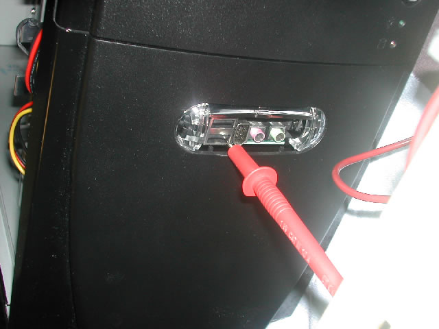
On the uA1-C, there is a header on the board for a serial port. It has been said that the uA1-I will have two ports on headers. What you need for access is a breakout cable to go from the header
to a serial port connector (usually a DB-9). You can bring the port out to a drive bay on the front of your computer with parts from FrontX.com.
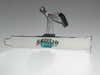
 | You can bring the connectors out to a PCI slot cover on the back with a simpler connector. There are two "standard" pinouts for this connector. These are sometimes called "Intel" and "Everex". The documents with the uA1 show the Everex wiring, but in fact the Intel wiring is correct (Thanks to KGrach for figuring this out). Showing the complete cable may be the clearest way to describe this. |
| This diagram shows the header from above the motherboard, and the DB-9 connector from the BACK, as you would see as you solder the wires. There should be pin numbers on the DB9 connector to verify this. | 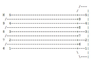 |
 | OK, so if you don't want to make your own, for the front ports, try the FrontX.com web store internal ports, serial 9 pin internal V2. For a rear mounted port on a PCI slot cover, there are many vendors. The cheapest I've seen is a1netusa.com, who offer the serial breakout as "9M-W" for $1.20 each, less in quantity. For uA1-I users, they offer the "9M9M-IO" for two bucks, with connectors and cables for both serial ports. Some vendors describe the two standards as "straight" or "crossover". |
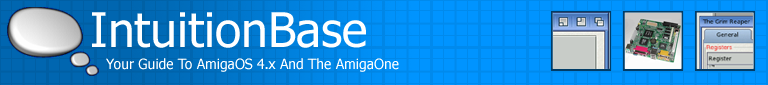
Another problem I had was the clearance for the connector.. The ten pins for the serial port are on the same header as the audio connections for line in/out and microphone. I can plug my serial cable in, but the bottom two pins of the audio connections left in and left out?) are then unreachable.
If you're not using front audio ports this should not be a problem, otherwise I'm working out an adapter to cover the difference.
IDE connections, 40 pin or 44?
 | The standard connector for desktop computers is 40 pins. For laptops, they shrunk the connector but added four more pins, so they could eliminate the power cord. The first 40 pins are identical on both types. The uA1-C has one of each. If you are planning on using a 2.5" drive, it will plug right into the 44 pin header. If you're only using a larger "desktop" drives, use the 40 pin header. If you want more than two bigger drives, you will need an adapter. All of the adapters I've seen so far are for plugging a laptop drive into a desktop machine.
|
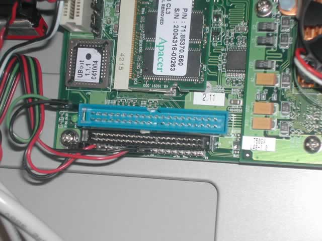
I wanted to plug a regular IDE cable into the mini connector on the board. The adapters are passive connectors, so they can be used either way. Just unplug the power connector on them and plug them into the 44 pin header on the micro board. I chose a small, molded connector from the same vendor as above. There is no keying on this adapter, on either side. This makes it possible for a misconnection. Following these steps carefully should insure a properly connected drive. | 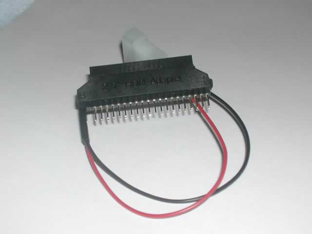 |
First, determine which end of the adapter is which. The power leads connect to pins 43 and 44 of the adapters "big" side. You'll notice that pins 41 and 42 are missing. Plug the "little" end of the adapter directly into the board. Be very careful to make sure it is centered in the 44 pin connector. The end of the connector with the missing pins and power leads should be away from the processor, and closest to the power LED.
Now you can prepare the "Big" side of the adapter. Most IDE cables have one pin "keyed" to prevent plugging in backwards. ("Keyed" means that one pin is missing, and the receptacle for it is plugged so that it fits only one way). Line up your IDE cable with pin one (Red stripe) closest to the processor.. If it won't plug in you'll have to clip one pin from the adapter. Be sure to get the right one! | 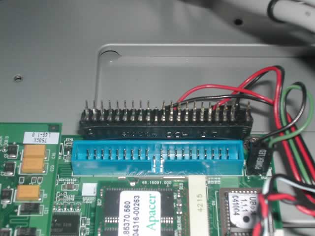 |
Biggest opportunities for mistakes, and their cures:
1> Plugging the adapter into the board backwards… The molded "R" and "B" are on the end furthest from the processor.
2> Plugging the adapter into the board off-center. Do a careful visual inspection.
3> Keying the connector wrong.. Pin one of the cable is closest to the processor.
Be careful on this one.. Mine worked first try, but I was sweating all the way.
Missing Parts
Sadly, paying top dollar for your MicroAmiga board does not mean you get everything you expect. There were a few things that are normally supplied with a motherboard that do not come with this one.
Most motherboards that I have bought come with an "ATX I/O Shield" that fits that specific board. This is a square plate that snaps into the back of most cases and provides the holes that the connectors poke through.
In approximate order from left to right, Keyboard and Mouse, 2 USB's and an ethernet jack, Parallel, VGA, S_Video and Composite Video, then the gameport and audio output jacks..The pattern of these connectors on the micro is unusual, because of the S-Video and composite video connectors where the second com port used to go. Most folks will take a common shield
 | with the two COM port openings and hack the second hole with a dremel or pair of snips to make it fit. This works, but looks a bit messy. I searched high and low to find the correct shield. I do not believe there is one being made. What I was able to find is a "mostly right" shield with no second COM port opening. I paid nine bucks for it, a dear price for such a simple plate. I'll be taking it to a machinist friend to get it punched with the correct holes.
|
 | Since I'm trying to be complete, another "missing" item, which seems trivial, were the nut connectors on the back for VGA and parallel ports. They usually have small threaded nuts so that when a cord is connected, the thumb screws can be tightened. That's right folks, the MicroA1 board (or at least MY micro board) comes without them. These can certainly be picked up at any PC shop for little or no cost, or pilfered from an old mobo. In the interest of providing a source for everything, I return to a1netusa.com, who offers a bag of 100 nuts as "S-HEX" for 3.50, and a bag of 100 washers, currently out of stock, as "S-RING" for another 3.50.
|
One last detail… a case badge. It's a detail that some motherboard makers provide. I got an "Antec" badge with my case, and also a got a "Boing Ball" case badge with my Micro board!! I don't know if it's normally included or just an extra from my dealer.
Too bad I didn't know it was coming, I had already pre-built my case and made my own badge using a do it yourself kit. Works great, and looks as good as the printer you use to print the image.
Beginners Corner
So you're new to building your own computer, and want to make sure everything works right? Here are a few tips that might help you to make fewer beginner errors.
Static Control.
Yes, it's not just a rumor. You need to be careful to avoid static damage whenever you are inside your computer. The "correct" method is with a static strap. It's a wristband with a wire attached. You wear the strap snugly around your wrist, in direct contact with your skin. You attach the other end to an earth ground. The case of your PC should be grounded when the power cord is connected. There are now "wireless" ground straps on the market. Forget them, they are worse than useless. They will only give you a false sense of security while you go on damaging your equipment. Some people skip the static strap and clip a jumper wire from ground directly to their metal watchband.
Yes, this will dissipate static, but it will also be EXTREMELY HAZARDOUS if you come in contact with line voltages while you are in the case. Don't ask me how I know that. Some other static-safe practices include touching bare case metal every time you approach the case, avoid working in low humidity areas. Avoid walking around or shuffling your feet while working, and avoiding varnished or shellacked work surfaces.
So, you ignore my warnings, and the computer works fine anyway. Does that mean you didn't damage it? Nope. Static damage most often appears weeks or months after the damage was done. I'll skip the details, please stay static-free.
Do not… DO NOT connect or disconnect anything while the power is on. Turn the power off at the switch behind your computer before doing any work. Leaving that switch on means the power supply is still providing standby voltage to parts of the system. There are exceptions to this… USB cables may be hot-plugged, as can MIDI cables, and SATA cables. These are the only exceptions that come to mind right now.
Opportunity Knocking...
It seems the next question is obvious…
Who will order the necessary parts and offer a uAOne owners kit?
1 serial breakout cable on a PCI slot cover, thin enough to not block the
audio pins.(Or dual serial for micro-I)
1 IDE 44 to 40 pin adapter, with keying pin clipped.
1 8 pin female to 10 pin male USB Header adapter.
1 custom ATX I/O Shield
6 threaded nuts for VGA, Gameport, and Parport connectors.
1 Amiga case badge
1 inexpensive static strap.
A decent S/PDIF IO on a PCI slot cover wouldn't hurt, either.
None of the above parts are expensive, though some could really be improved upon, like making an IDE adapter that can't be plugged in off center or backwards.
Seems like a real opportunity to make money and help the Amiga to be more "accessible" to the public.
What's next?
Ask for what you want to see added here. I'll kick it in if I can.
I'll also add whatever I experience as I build my box.
One proposal is "how to read Classic Amiga hard drives on your new AOne"
Standard Disclaimer
I have no association with any of the companies listed here. I will make no proceeds from their sales. I provide this information freely, but assume no responsibility for it's accuracy or for your interpretation or mis-interpretation of the information provided.
I'll probably help anyone who asks nicely, but I reserve the right to ignore anyone for any reason or lack of reason that I see fit.
This document is copyright 2005 Lyle Hazelwood, and may be distributed freely
under the following conditions: Must be distributed in it's original form, without editing.
May not be sold for profit without prior written consent of the author. May not be used for the development or testing of nuclear or biological weapons. Use for the detection of mythical "Weapons of Mass Detruction" is permitted. ;)
Written by Lyle Hazelwood (Published: 2005 at ncscaug.us)