This article was originally published on amigaportal.cz in November 2022.
Article is a loose continuation of the previous two parts about AmigaOne XE:
AmigaOne XE - "quickly and easily",
AmigaOne XE - AGP and PCIe graphics cards
and discusses the hardware interrupts in this Amiga. There will be more theory and more technique here. Since I didn't really understand the PCI interrupt system in XE, I had to look it up and you can find that here as well. And I have to say it's a lot more complicated compared to today's PCIe system.
So this article will be more like a small textbook for beginners and intermediate users on the topic of "PCI legacy interrupts". And textbooks tend to be boring, so be prepared for that.
1. Why are we doing all this?
Definitely to know a bit more about my AmigaOne XE ( and not only about it, the interrupts will look very similar for all AmigNG first generation, AmigaOne SE, Micro A1-C, Pegasos 1 and Pegasos 2 ) .
And also because some things don't work in our XE and the latest official U-Boot 1.1.1 firmware can't initialize PCI cards behind the bridge properly.
What I would like to try is to enable interrupts for PCIe cards behind the PCI-PCIe bridge. Small thing, right?
2. Documentation
Since I didn't understand this issue very well, I had to read some documentation this time, which I really don't like to do.
Whoever wants to check my procedures and considerations, I recommend this literature:
- PCI localbus specification rev. 2.2
We know that the arbiter for the PCI bus is the northbridge Articia S. I could not find the manual of the Articia S ( only the datasheet ), but I assume that the Articia S has PCI rev. 2.2. Fortunately, there is not much to go wrong, the version 2.1 Articia meets for sure ( v.2.1 introduced 66 MHz, which Articia can do ), version 2.2 probably ( it's just a minor modification of v.2.1 ) and version 2.3 Articia S doesn't meet anymore ( v.2.2 disabled 5V PCI cards ). Moreover southbridge of XE is PCI v.2.2 compatible, so we'll take PCI v.2.2 as valid.
Next, we'll deal with PCI-PCI bridges ( and PCI-PCIe bridge is also the case ), so we need:
-PCI-to-PCI Bridge Architecture Specification rev.1.1
This is the version that was valid at the time of PCI v.2.2.
-PCI Express-to-PCI/PCI-X Bridge Specification rev.1.0
This version is met by both of our tested PCI-to-PCIe bridges.
-PLX Technology: PEX 8112-AA PCI Express-to-PCI Bridge Data Book
-Pericom: PI7C9X111SL PCI Express-to-PCI Reversible Bridge Datasheet
And if you go deeper into the documentation, we are interested in the Reverse Bridge ( i.e. PCI motherboard and PCIe card ) and the transparent bridge feature. Both of our bridges are transparent, which simply means that those commands and data that are common to both PCI and PCIe standards are passed straight through.
3. PCI bus inside AmigaOne XE in more detail
This time we are only interested in PCI from the northbridge Articia S, but in more detail.
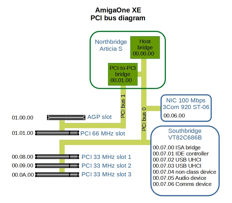
This is how the PCI buses are addressed in the AmigaOne XE. The PCI address is in the form XX.YY.ZZ and means:
XX = bus number (bus nr.)
YY = device number on the bus (device nr.). The device is for example a PCI card.
ZZ = device function (function nr.), usually the device has one function ( .00 ), but it can have more.
The diagram is based on data from Ranger and can be seen here:
00.00.00 = Host bridge. So something like a root hub in modern PCIe. The starting point of the controller ( PCI arbiter ).
00.01.00 = PCI-to-PCI bridge. You can see that PCI bus 1 (AGP+PCI 66) does not have its own host bridge (root hub in today's PCIe terminology) but is connected to PCI bus 0 via a PCI-to-PCI bridge. This bridge is therefore the first (00.01.00) device after the Host bridge on PCI bus 0. PCI bus 1 starts behind this bridge.
This also explains why we cannot use the PCI 66 MHz slot for PCIe cards. The connection line would look like this:
Host bridge - PCI-to-PCI bridge - PCI-to-PCIe bridge - PCIe graphics card
That is, behind two bridges. And the card behind two bridges can no longer be initialized by U-Boot.
00.06.00 - Ethernet on motherboard.
00.07.00 - Southbridge VT82C686B. You can see that the southbridge is a single PCI device ( .07. ), but it has multiple functions. In fact, you will find most of the XE's internal peripherals here: IDE, USB1.1, audio, serial.
00.08.00 - this is the address of the device ( card ) in PCI 33 MHz slot 1.
00.09.00 - this is the address of the device ( card ) in PCI 33 MHz slot 2.
00.0A.00 - this is the address of the device ( card ) in PCI 33 MHz slot 3.
01.00.00 - this is the address of the device ( card ) in the AGP slot. Note that it is already on a different PCI bus ( 01.xx.xx = PCI bus 1)
01.01.00 - this is the address of the device ( card ) in the PCI 66 MHz slot.
Rebus - PCI diagram:
And try to think if you don't find something strange in this scheme. At the end of the article you will find out what.
4. What the PCI interrupt system looks like in AmigaOne XE
In AmigaOne XE, the PCI interrupt controller function is provided by our VT82C686B southbridge.
If you want to look something up, this is the early PCI interrupt system, now called PCI Legacy, and not the newer PCI MSI ( Message Signalled Interrupts ) version.
The assignment of interrupt lines is done by the firmware. In our case it is U-Boot. We have the latest official version from Hyperion: U-Boot 1.1.1.
4.1 basic INTx# pin assignment for PCI devices
Each PCI device can use up to four different hardware interrupts to signal an interrupt. Four physical pins, INTA#, INTB#, INTC# and INTD#, are reserved for them on the PCI connector.
( For interest, on PCI connector these are the pins A6, A7, B7, B8 ).
The AGP device has only two hardware pins INTA#, INTB# ( A6, B6 ).
Importantly, these signals are physically connected to the interrupt controller.
( Definition: IRQ Pin = an indication of which physical pin on the PCI card the function uses )
So the data wires of the PCI bus are connected to the northbridge as in the Diagram 3.1. But the interrupt pins lead to the interrupt controller, i.e. the southbridge, where they are connected to the physical interrupt controller pins as follows:
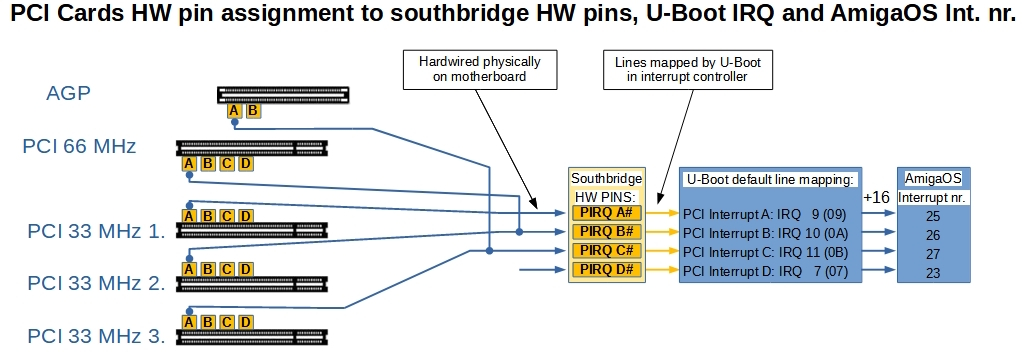
Squares A, B, C, D are the physical interrupt pins INTA#, INTB#, INTC# and INTD# on PCI cards.
PIRQ A#, PIRQ B#, PIRQ C#, PIRQ D# are the physical pins on the interrupt controller, the southbridge (ours has only four pins, generally there can be more).
The PIRQ A# is connected to a device in PCI 33 MHz slot 1.
Devices in PCI 66 MHz slot and PCI 33 MHz slot 2 are connected to PIRQ B#.
Devices in AGP slot and PCI 33 MHz slot 3 are connected to PIRQ C#.
There is nothing connected to PIRQ D# in this diagram.
Here again, a little digression:
It is wise to think about PCI card seating. If we have, for example, an AGP card ( I estimate that it will have the highest number of interrupts during operation ), which is connected to PIRQ C#, it is probably not optimal to put a second graphics card or perhaps a SATA controller in PCI 33 MHz slot 3 ( with which it shares hardware interrupts ). Conversely, when I tried PCIe cards, I put them in 33 MHz slot 3, because the AGP card was not populated and therefore did not share the interrupt pin.
In the older ISA architecture, each device had to have a unique interrupt number. I don't know if you remember, but in the old PC XT/AT, when using multiple cards, it was often necessary to set the interrupt numbers manually so they didn't conflict.
However, in the PCI architecture, physical hardware interrupts can already be shared and conflicts are resolved by their different priority.
The interrupt controller in the AmigaOne XE is of the APIC ( Advanced Programmable Interrupt Controller ) type, it contains an interrupt router and with it U-Boot maps individual HW interrupts to IRQs, i.e. assigns lines.
(Definition: Interrupt line = configuration, determines what IRQ number is assigned to each PCI function)
In the Diagram 4.1 you can see how the lines are assigned in AmigaOne XE ( if you leave the default settings in the U-Boot menu "PCI/AGP") :
Hardware PIRQ A# (marked as PCI Interrupt A in U-Boot) is mapped to IRQ 9 (0x09)
Hardware PIRQ B# (marked as PCI Interrupt B in U-Boot) is mapped to IRQ 10 (0x0A)
Hardware PIRQ C# (marked as PCI Interrupt C in U-Boot) is mapped to IRQ 11 (0x0B)
Hardware PIRQ D# (marked as PCI Interrupt D in U-Boot) is mapped to IRQ 7 (0x07)
I admit that I don't understand the APIC mechanism, I don't know how to look inside the controller from AmigaOS and see the routing table and I won't install Linux because of that. I wouldn't be able to change the controller settings in AmigaOS anyway. For now, we just need to know that a value of 16 ( 0x10 ) is added to the lines mapped this way and these interrupt numbers are used in the operating system in the Interrupt Handler.
My guess is that this is based on the previous ISA model where the first 16 interrupts were reserved for ISA interrupts.
(Definition: Interrupt number = PCI function interrupt number in the operating system )
4.2 small exercise in Ranger
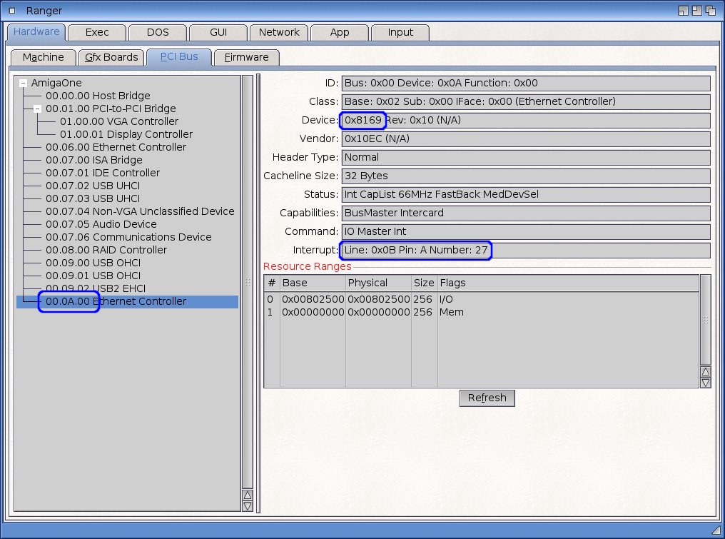
Figure 4.2 shows the output from the Ranger program. What we see:
- The Ethernet card has address 00.0A.00, i.e. it is plugged into PCI 33 MHz slot 3
- this is type RTL8169
- has interrupt line 0x0B ( = 11 ) assigned, the hardware interrupt is on pin A of the PCI card and the interrupt number in AmigaOS is 27 ( 11+16=27 ).
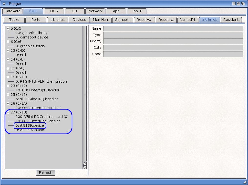
In Figure 4.3 we see:
- rtl8169.device has interrupt number 27 ( 0x1B )
- the interrupt priority of this device is 5
- interrupt 27 is shared with three other devices and the highest priority 100 has the graphics card.
4.3 complete INTx# pin assignment for PCI functions
But what if the PCI card has more functions and even more interrupts? Like the southbridge in diagram 3.1. But not only the southbridge, some common cards have multiple functions. They may need more physical interrupts.
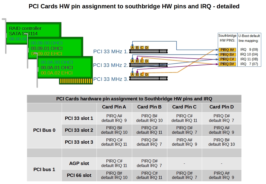
This is where it gets more complicated. In diagram 4.4 we see three PCI cards:
- SATA controller in PCI 33 MHz slot 1: has only one function and one HW interrupt ( pin A = INTA# ). This is physically connected to the PIRQ A# of the controller.
- USB 2.0 card in PCI 33 MHz slot 2: it has three functions and each function has its own HW interrupt.
00.09.00 USB OHCI is connected to pin A of the PCI card and physically connected to PIRQ B# of the controller.
00.09.01 USB OHCI is connected to pin B of the PCI card and physically connected to the PIRQ C# of the controller.
00.09.02 USB EHCI is connected to pin C of the PCI card and physically connected to the PIRQ D# of the controller.
Pin D on this card remains unused.
You can see that each function with its own interrupt is connected to a different physical pin of the card and the controller, simply by shifting one position each time.
- USB 2.0 card in PCI 33 MHz slot 3: this is the second USB card at PCI address 00.0A.00 to .02 and we can see that the hardware connections are again shifted by one.
A complete overview of the hardware pins and mapped lines can be found in the table at the bottom of diagram 4.4.
4.4 PCI header
Each PCI function has its own configuration space in memory. The basic one is called a PCI header. There are several types of headers. Type 00h is the header for standard PCI functions and type 01h is the bridge header.
PCIe devices generally have a slightly different header, but what the PCI bus sees from the PCIe card is just the 00h header and from the PCI-PCIe bridge just the 01h header. So for us, in this case, PCI and PCIe are the same.
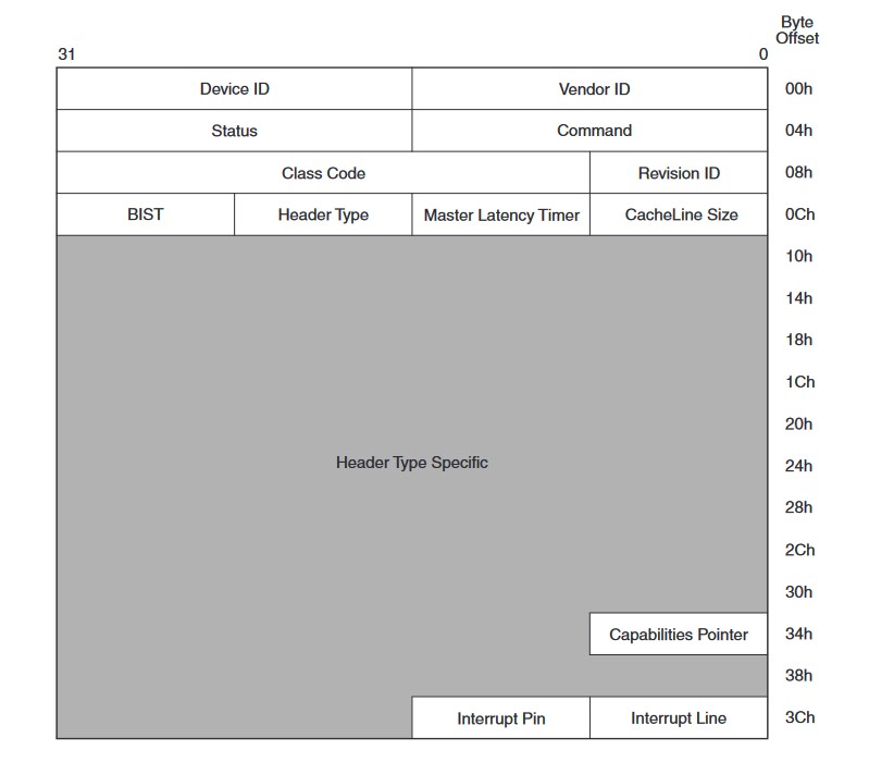
This is what a PCI header looks like, the white fields are common to all header types and will be of interest to us.
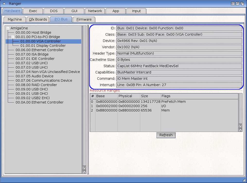
And note that Ranger just shows the PCI header data.
5. Exploring the PCIe graphics card behind the PCI-PCIe bridge
So we already know a bit of the theory and now let's take a closer look at what happens in our Amiga when initializing a PCI device.
We already know that our graphics card behind the PCI-PCIe bridge is not properly initialized. But what does such a correct initialization look like? Well, for that you would need to read the specs in even more detail than I did and probably a deeper knowledge of AmigaOS. So let's use a little comparative method.
I took the PCI-PCIe bridge and the HD7750 card and plugged them at first into AmigaOne XE and then into Sam440ep-flex.
This should be more or less equivalent of using bridges and cards. And we know that in Sam440ep-flex it works as it should.
The values will certainly vary in PCI device addresses, line assignments and interrupt numbers - all are dependent on the specific computer design, but other characteristics "should be the same".
For Sam440ep-flex, the arbiter for the PCI bus is the AMCC440 CPU itself. The PCI here meets the v2.2 standard. But I think advanced MSI functions is not used in AmigaOS - just look at the mapped interrupt numbers - again, they are all offset by 16 and there is nothing more sophisticated.
5.1 AmigaOne XE and Sam440ep-flex bridges comparison
We start by looking at how bridges are initialized.
Comparing the same PCI-PCIe bridge on AmigaOne XE and Sam440ep-flex we find the following:
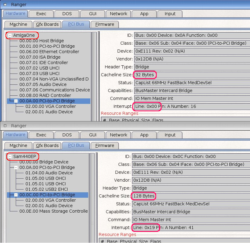
Interrupt Line: AmigaOne XE: 0x00, Sam440: 0x19
The bridge on Sam440ep has a mapped interrupt line, so it can generate interrupts (the actual line number is not important here, it certainly varies between different types of computers).
AmigaOne XE has interrupt line 0x00. While this is generally speaking a valid interrupt value, the southbridge XE interrupt routing table defaults to 0x00 Disabled. The table is programmable, but since I don't have a tool in AmigaOS to look at it, I assume that a bridge set up this way does not generate an interrupt. At least no value appears in the AmigaOS interrupt handler.
Generally speaking, it is not a mistake if the bridge does not generate interrupts. Modern PCIe card does not have hardware INTx# pins and does not generate PCI Legacy interrupts. It generates instead PCIe messages Assert_INTx / Deassert_INTx. The transparent bridge translates these messages received from the PCIe card into PCI Legacy hardware INTx# interrupts on the PCI bus.
What the Interrupt Line value is set for the bridge only tells what interrupt number the bridge will generate for itself ( not for the card ). I admit I don't know if the bridge itself generates anything at all. Probably not, because there is nothing in the Interrupt handler in Sam440 either.
Next it differs in the Cacheline size: AmigaOne XE 32 B, Sam440 128 B. It is the cache size that is used when Memory Write, Invalidate and Memory Read transactions are terminated.
If the bridge itself generates these transactions or forwards them between buses, it must contain this cache.
If the cache is 0 B, everything is of course slower. The difference in cache size is probably due to the different properties of the PCI arbiter. All PCI devices in the AmigaOne XE, if they have a cacheline, have only 32B.
We also see that most of the other data are the same. And it should be. It's the same bridge.
So we would like to set up an interrupt line at the bridge in XE. I have a PCI-PCIe bridge in PCI 33 MHz slot 3, so according to Figure 4.1 we would like a value of 11 ( 0x0b ).
Knowing that this may be unnecessary, but it shouldn't hurt if it works on Sam.
We won't touch the cacheline, 32 B is fine for XE.
5.2 Comparison of graphics cards behind the bridge in AmigaOne XE and Sam440ep-flex
Now let's compare the HD7750 graphics card data behind the PCIe bridge in the AmigaOne XE and Sam440ep-flex:
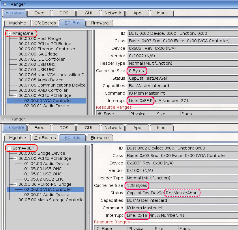
Again, they differ in Interrupt Line: AmigaOne XE: 0xFF, Sam440: 0x19
And here we can see that it's wrong. The value 0xFF means that the line is not set and the device does not generate the interrupt at all. So for the AmigaOne XE neither the bridge nor the graphics card generates an interrupt.
Again, there is a difference in cacheline size Cacheline size: AmigaOne XE 0 B, Sam440 128 B. And this also bothers us. This means that the XE does not use cache for memory reads and writes.
And further in the Status register: the Sam440 has an extra RecMasterAbort, but let's ignore that, it's an operational state on the bus.
So we would like to set the interrupt line on the card in XE to 11 ( 0x0b ) again. According to the PCI bus specification, the first device after the bridge maps to pin A of the bridge card, so here again 11 ( 0x0b ). There is a nice big table Interrupt Routing in the specification of PCI bridges. Anyone who wants to can look it up.
Next, we will try to set the cacheline value for XE to 32 B. In the header, this value is given in DWORDS ( 4 Bytes ), so the desired value will be 32/4 = 8 (0x08).
6. PCI bus status and what exactly we want to fix
In our case, the position of the cards on the bus is as follows:
PCI 33 MHz slot 1 ( adr 00.08.00): SATA controller
PCI 33 MHz slot 2 ( adr 00.09.00): NIC 1 GbE
PCI 33 MHz slot 3 ( adr 00.0A.00): PCI-to-PCIe bridge
- we have a new PCI bus 02 behind the bridge:
address 02.00.00: PCIe graphics card
I already mentioned this in the text, but now we'll set it explicitly. You can of course put the PCIe bridge elsewhere, but if you have it like this, the PCI function addresses as I list them below will be valid. If you use a different slot for the bridge, you must change the addresses accordingly.
So we want to set this:
Bridge:
- address 00.0A.00, Interrupt line = ( byte 3Ch in PCI header, see Figure 4.5 ) = 0x0b
Card:
- address 02.00.00, Interrupt line = ( byte 3Ch in PCI header ) = 0x0b
- address 02.00.00, Cacheline = ( byte 0Ch in PCI header ) = 0x08
7. Correction of PCI header settings
That's easy to say, but how do we do it?
7.1 U-Boot commands
Fortunately, in U-Boot XE we have some powerful commands for working with the PCI bus, which we can use to view and change settings on the PCI bus:
pci [bus] [long] - short or long list of PCI devices on 'bus'
pci header b.d.f - show header of PCI device 'bus.device.function'
pci display[.b, .w, .l] b.d.f [address] [# of objects] - display PCI configuration space (CFG)
pci next[.b, .w, .l] b.d.f address - modify, read and keep CFG address
pci modify[.b, .w, .l] b.d.f address - modify, auto increment CFG address
pci write[.b, .w, .l] b.d.f address value - write to CFG address
7.2 Exploring the PCI bus in U-Boot
First, we'll take a look at what we'll be doing in the U-Boot. In U-Boot, we enter the command line.
First we will look at the devices on PCI bus 0 and bus 2:
Code:
] pci 00
Scanning PCI devices on bus 0
BusDevFun VendorId DeviceId Device Class Sub-Class
_____________________________________________________________
00.00.00 0x10cc 0x0660 Bridge device 0x00
00.01.00 0x10cc 0x0661 Bridge device 0x04
00.06.00 0x10b7 0x9200 Network controller 0x00
00.07.00 0x1106 0x0686 Bridge device 0x01
00.07.01 0x1106 0x0571 Mass storage controller 0x01
00.07.02 0x1106 0x3038 Serial bus controller 0x03
00.07.03 0x1106 0x3038 Serial bus controller 0x03
00.07.04 0x1106 0x3057 Build before PCI Rev2.0 0x00
00.07.05 0x1106 0x3058 Multimedia device 0x01
00.07.06 0x1106 0x3068 Simple comm. controller 0x80
00.08.00 0x1095 0x3114 Mass storage controller 0x04
00.09.00 0x1033 0x0035 Serial bus controller 0x03
00.09.01 0x1033 0x0035 Serial bus controller 0x03
00.09.02 0x1033 0x00e0 Serial bus controller 0x03
00.0a.00 0x12d8 0xe111 Bridge device 0x04
]
] pci 02
Scanning PCI devices on bus 2
BusDevFun VendorId DeviceId Device Class Sub-Class
_____________________________________________________________
02.00.00 0x1002 0x683f Display controller 0x00
02.00.01 0x1002 0xaab0 Multimedia device 0x03
Above we see our bridge ( 00.0a.00 ) and graphics card ( 02.00.00 ). If you have different card setup than me, check here for the correct PCI addresses.
Now let's take a look at the PCI header of the bridge:
Code:
] pci header 00.0a.00
vendor ID = 0x12d8
device ID = 0xe111
command register = 0x0007
status register = 0x02b0
revision ID = 0x02
class code = 0x06 (Bridge device)
sub class code = 0x04
programming interface = 0x00
cache line = 0x08
latency time = 0x20
header type = 0x01
BIST = 0x00
base address 0 = 0x00000000
base address 1 = 0x00000000
primary bus number = 0x00
secondary bus number = 0x02
subordinate bus number = 0x02
secondary latency timer = 0x00
IO base = 0x21
IO limit = 0x21
secondary status = 0x2000
memory base = 0xa000
memory limit = 0xa000
prefetch memory base = 0x9001
prefetch memory limit = 0x9ff1
prefetch memory base upper = 0x00000000
prefetch memory limit upper = 0x00000000
IO base upper 16 bits = 0x0000
IO limit upper 16 bits = 0x0000
expansion ROM base address = 0x00000000
interrupt line = 0x00
interrupt pin = 0x01
bridge control = 0x0018
]
] pci display 00.0a.00
00000000: e11112d8 02b00007 06040002 00012008
00000010: 00000000 00000000 00020200 20002121
00000020: a000a000 9ff19001 00000000
00000030: 00000000 00000080 00000000 00180100
]
In the detailed and compact list we can see the cacheline and interrupt line values additionally highlighted with bold text.
Next is the listing for the graphics card with the highlighted values:
Code:
] pci header 02.00.00
vendor ID = 0x1002
device ID = 0x683f
command register = 0x0007
status register = 0x0010
revision ID = 0x00
class code = 0x03 (Display controller)
sub class code = 0x00
programming interface = 0x00
cache line = 0x00
latency time = 0x00
header type = 0x80
BIST = 0x00
base address 0 = 0x9000000c
base address 1 = 0x00000000
base address 2 = 0xa0000004
base address 3 = 0x00000000
base address 4 = 0x00002001
base address 5 = 0x00000000
cardBus CIS pointer = 0x00000000
sub system vendor ID = 0x1043
sub system ID = 0x0427
expansion ROM base address = 0x00000000
interrupt line = 0xff
interrupt pin = 0x01
min Grant = 0x00
max Latency = 0x00
]
] pci display 02.00.00
00000000: 683f1002 00100007 03000000 00800000
00000010: 9000000c 00000000 a0000004 00000000
00000020: 00002001 00000000 00000000 04271043
00000030: 00000000 00000048 00000000 000001ff
7.3 Correcting PCI header settings
So what U-Boot didn't do, we'll try to fix. If this is your first time, take a deep breath and let's get started:
Code:
] pci write.b 00.0A.00 3c 0b
] pci display 00.0a.00
00000000: e11112d8 02b00007 06040002 00012008
00000010: 00000000 00000000 00020200 20002121
00000020: a000a000 9ff19001 00000000 00000000
00000030: 00000000 00000080 00000000 0018010b
and we can see that the PCIe bridge interrupt has changed to the desired value. Ufff. Let's move on to the graphics card:
Code:
] pci write.b 02.00.00 3c 0b
] pci write.b 02.00.00 0c 08
] pci display 02.00.00
00000000: 683f1002 00100007 03000000 00800008
00000010: 9000000c 00000000 a0000004 00000000
00000020: 00002001 00000000 00000000 04271043
00000030: 00000000 00000048 00000000 0000010b
and we see that the interrupt and cacheline have changed for the graphics card.
Then just boot into the system and voila:
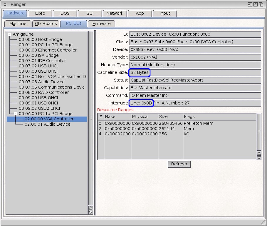
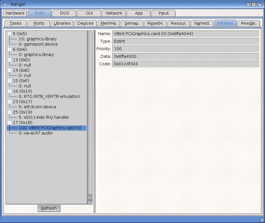
So it worked!
8. Using the PCI/AGP U-Boot Menu
It would also be possible to use other U-Boot options, other interrupt line settings.
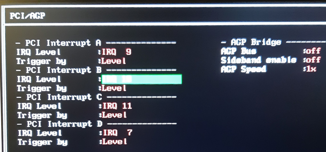
In the "PCI/AGP" menu we can set the "IRQ level" for PCI interrupts in addition to the AGP bridge.
So modify the line mapping to different values. For each of the four physical pins of the controller (in the menu marked PCI interrupt A = PIRQ A#, etc.) it is possible to select one of the values 9, 10, 11, 13, 7.
So far we have been working with the default settings, as shown in the figure 8.1.
If you change the settings just by shifting ( for example PCI int A = 10, B = 11, C = 7, D = 9), the lines and interrupt numbers will change, but from the user and system point of view it doesn't matter. That doesn't help us.
Mapping all physical interrupts to the same interrupt lines is not reasonable and doesn't make much sense. Simply multiple devices would have the same interrupt number.
And if you use the value 13 ( 0xD ) for one of the interrupts, nothing happens - nothing is mapped to 13.
In the routing table of the controller, interrupt 13 is marked as "Reserved" and I don't know exactly what it does. The fact is that no interrupt 29 ( = 13+16 ) appears in the AmigaOS Iterrupt Handler.
And what else we can set in the U-Boot menu is how the interrupt will be generated:
"Trigered by level" - interrupt is generated continuously and only the process of resolving the interrupt will terminate it. Normally this is the correct setting. The interrupt is resolved as long as the device reports the interrupt.
"Triggered by edge" - interrupt is generated only once ( when physical signal grows ). So sometimes it may happen that no one resolves the interrupt.
This setting is not normally used. It should only be used if the system is freezing up when handling interrupts - that is, if the device is overwhelmed with requests and the driver is not written ideally.
So changing the interrupt lines to other numbers will not help us in our efforts. If anyone would like, they can experiment further with line value 13 ( 0xD ). It would be interesting to know why this option is there and what to use it for.
9. Automation
We can set the correct interrupt on a PCIe graphics card. But it would be impractical to re-enter pci write commands every time you boot. We would soon get tired of that. Fortunately, we can automate this.
In AmigaOS we create a new environment variable, "pcifix", in the shell. You can of course also do this from the U-Boot command line, but it is more convenient this way. > nvsetvar pcifix "pci write.b 00.0a.00 3c 0b; pci write.b 02.00.00 3c 0b; pci write.b 02.00.00 0c 08"
And then we check: > nvgetvar pcifixpci write.b 00.0a.00 3c 0b; pci write.b 02.00.00 3c 0b; pci write.b 02.00.00 0c 08
Then we can enter only one command at each boot in the U-Boot command line:
] run pcifix
And we got it fixed without the risk of a typo.
And if we're happy with the result of the PCI setup fix and we're done testing, we'll do a full automation. Let's modify the "menuboot_cmd" variable as follows:
> nvsetvar menuboot_cmd "run pcifix; boota; boota; boota"
This will start the patch automatically every time we boot into AmigaOS.
But don't forget to return this variable to its original state when you remove the PCIe card from your Amiga.
10. Other versions of U-Boot
All tests were done with the latest official version of U-Boot from Hyperion, i.e. 1.1.1.
However, other versions were available to beta testers but were never officially released.
Apart from the fact that the higher versions should allow booting from other PCI cards ( SiI3114, SiI35121 ) there are other differences for us:

Not a single U-Boot can work with the PCIe bridge PEX8111.
But higher versions of U-Boot 1.1.6 and 1.2.0 can already correctly assign an interrupt line to the graphics card behind the PCI-PCIe bridge. The card cacheline remains zero for all of them.
11. Conclusion
After manually adjusting the interrupts and cacheline, the video card speed increased only slightly.
MPlayer has sped up by two seconds: from 307.905 seconds to 305.879 seconds.
ioquake3 sped up from 21.5 FPS to 21.9 FPS.
So in normal operation the user will not notice anything. I guess it would take a faster CPU than my 800 MHz to make the differences bigger. But we can be satisfied that we have fixed the U-Boot bugs and understand more things again.
Nice thing is that before the modification the serial debug in RadeonHD looked like this:
Code:...RadeonHD.chip (0): RadeonHD card successfully openedRadeonHD.chip (0): UBoot has not initialized the graphics card's interrupt line. Disabling interrupts.RadeonHD.chip (0): Please upgrade your UBoot firmware.a1ide.device 53.22 (28.6.2017)[a1ide/dev_init] a1ide_timeout : '10', adjusted ata timeout to 10...
And after our modification it looks like this:
Code:...RadeonHD.chip (0): RadeonHD card successfully openeda1ide.device 53.22 (28.6.2017)[a1ide/dev_init] a1ide_timeout : '10', adjusted ata timeout to 10...
As another big free bonus, we get that we can use the so-called "combo cards" in our AmigaOne XE. These are cards that contains a PCI-to-PCI bridge and multiple devices behind it. For example, SATA and Firewire or SATA and USB. The truth is that most of them have drivers only for Linux, but still. We now know how to make them work. It works the same way like our graphics cards: all functions behind the bridge has no initialized interrupt by U-Boot. So we simply set correct interrupt.
Rebus - PCI diagram explanation ( from the beginning of the article ):
So you won't find a solution here, just a consideration.
According to the PCI specification, if 33 MHz and 66 MHz devices are together on one bus, the entire bus operates at 33 MHz. So according to this, PCI-to-PCI bridge 00.01.00, which separates PCI bus 1 ( 66 MHz ) would only work at 33 MHz. So the graphics card can be as fast as it wants, but the transfer rate may then be limited to 133 MB/s ( PCI bus 0, 33 MHz ).
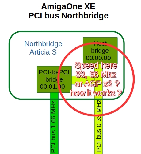
If the Artticia S were actually internally designed as Ranger shows, the data from PCI bus 1 66 MHz would never reach a transfer rate greater than 133 MB/s.
It doesn't have to be that way, it is just a diagram based on the data from the Ranger - that is, how the PCI is seen from the firmware and operating system. In reality, both the Host bridge ( 00.00.00 ) and the PCI-to-PCI bridge ( 00.01.00 ) are inside the ArticiaS northbridge and may be connected differently. Unfortunately, I was not able to get a detailed manual for the Articia S.
But the fact is that Pegasos 2 ( with northbridge Marwell Discovery 2 ) does not have one Host bridge and PCI-to-PCI bridge, but two independent Host bridges for 66 MHz and 33 MHz busses.
Pegasos 2 ( PCI 66 MHz ) achieves a VRAM write speed of 221 MB/s.
The AmigaOne XE ( AGP x2 / PCI 66 MHz ) achieves write speeds to VRAM of only 111 MB/s, even for AGP x2 setting.
Strange, isn't it?
Special thanks to Evillord68 for his help.
